Monday 28 November 2016

Sky Dome

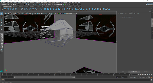
This is a render from the inside of my sky dome

This is a render from outside my sky dome

In this practical we learned a very good way of creating a sky dome,  I have made a sky dome before, but I simply inverted the textures on a sphere, but that method can cause issues in terms of lighting and shadows. With the way we have learnt to implement a sky dome here, we disable the parts of the sphere that would block light and cast shadows, and we also learn to use layers to make objects such as the sky dome completely untouchable until we make it otherwise, this is an incredibly powerful tool as it will allow us to choose exactly what will be visible on the screen and can stop us from touching objects that we don't want to be moved, layering also makes for a cleaner project.

Friday 25 November 2016

Tie Interceptor model part 6


I have added some finishing touches to my interceptor, such as extruding the engine in the back to look more hollow, and deleted some overlapping faces, I have now completed my final model, and all 3 are ready for submission.

Thursday 24 November 2016

Tie Interceptor model part 5

After noticing a piece I left off of the wings, I extruded it and made the guns on the end of the wings out of cylinders, then I deleted the right wing and duplicated the fixed left wing over to the right side, using the same method as before.

Wednesday 23 November 2016

Tie Interceptor model part 4


I have added the gun on to the wing of the tie fighter, I made this gun by first extruding a cube along the path shown by the reference image, and then adding more shapes for the detailing, and for the barrels of the guns I created two cylinders and extruded them into shape. I have also used the extruded cubes and Boolean difference to cut the shapes into the wings of my ship, however due to an unkown error, I had to manually extrude in the indentation on the bottom left of this image.


To make sure I avoided another error like last time, I extruded the indentations into the inside of the wing.
I then duplicated the left wing group and scaled it by -1 on the appropriate access as I have done for my other two models. This has made me my right wing.

Tie Interceptor model part 3


I have now added extrusions into the top of the sphere where there are vents in the ship, I have also made two small guns for the front of the ship with some simple polygon spheres and added the details to the connector from the body to the wing of the interceptor, this makes it look much more like it does on the reference images, I didn't add too much detail to this ship as most of them are very small and minor, so they would be much better off textured on rather than modelled on.

Tuesday 22 November 2016

Tie Interceptor model part 2


Here I began to set to work on making my cockpit, I started by deleting some faces off of the circle where the cockpit would sit, I then created an octagon and aligned it with the middle of the cockpit, which is an octagon in the reference images. I then added edge loops all around the octagon and extruded them to make small lines coming out of the octagon and connecting to the edge of the ships body, these will act as the frames of my cockpits window.


Here I have finished creating the frames and having pulled them back a bit to give depth to the cockpit, so it isn't just a flat surface.


Here I have Finished creating and extruding the shapes for the windows.


Now I have aligned the windows with the window frames and snapped the vertices into place., so there are no overlapping faces, and the cockpit looks exactly as it should.


Finally I moved my cockpit into my ship and aligned it perfectly by adding edge loops into the cockpit and moving the vertices so that they align with the vertices on the  rim of the body of the ship, this allowed me to move the cockpit perfectly in place with no overlapping faces.

Monday 21 November 2016

Tie Interceptor model part 1


As with my two previous models I have created and set a new project and set up my viewports and image planes.


When I first began to make this model I started with the body, however I quickly began having trouble with the cockpit and how to fit it properly into the body, so I decided to do the easier part, the wings first and come back to the cockpit later, so I would have the most time to do the part I was struggling with. Here I have extruded out all of the shapes and merged the vertices at the tips of the wings to create the point that the interceptor has, I then tilted the bottom and top portions of the wing to match the reference image. I added the shapes on the outside of the wing for later on when I will use them to bool, difference and cut their shapes out of the wing.


With the basic shape for the wing complete I went back to the body and added the engine onto the back of the interceptor, I did this by simply adding a cylinder to the back of the ship and deleting any face on the sphere that were no longer visible because of the cylinder.

Y- wing model part 5


And here is my final completed y-wing model, with all of the objects grouped and named appropriately to make the outliner cleaner and easier to navigate. I have added some more minor details and been comparing it to other images of a y-wing to ensure it looked like them, and I am satisfied with my end product.


Sunday 20 November 2016

Y- wing model part 4


As you can see in the image above I have used multiple cylinders to recreate the piping and wiring shown on the reference image of the ship, I have done this in order to make the ship look more realistic once it is textured, with the most prominent details sticking out and the more minor ones textured on, creating a realistic looking y-wing.


In order to create the right engine I had to delete the middle beam going through the body that I originally created as the wings connector, and instead I duplicated the Left wing group and scaled it by -1 across the appropriate access, which, as I have discussed before, places it perfectly opposite its counterpart.

Friday 18 November 2016

Y- wing model part 3


I have now added the base bullet like shape of the left engine, I made this shape by cutting a sphere in half and scaling it to make it longer, and then making sure it has the same number of divisions as the cylinder and aligning all of the edges as closely as I could. I then created on of the four poles that connects the rear of the engine with the front., I did this by making and rescaling multiple objects.


In this image I have now added more extrusions to make the engine look more like it does in the reference image. I have also added the rear of the engine and used the duplicate special tool to duplicate the pole connecting the rear to the front of the engine perfectly around the cylinder. I have also added the cannon to the top of the cockpit, this is a pretty simple object made of many different shapes.

Thursday 17 November 2016

Y- wing model part 2


Since my last post, I have added the windows into the cockpit by extruding the shape of the window and then the depth, I have also extruded the small gap in the tip of the nose and added the two guns that are in the tip of the ship.

Monday 14 November 2016

Y- wing model part 1


As with my x-wing, I first made and set a new project, and set up my viewports so that the reference image lines up perfectly with each other.


I started off my y-wing by first modelling the nose of the ship, moving between viewports to get the shape right, and then adding in the cockpit as a separate object, and finally modelling the central most part of the body, following the reference image.

Friday 11 November 2016

Materials 2


In this lesson we continued to go into more detail about materials, the first thing that we went through was how to use projection mapping, projection mapping is different to setting a texture as an image, it is more like painting it on top of the object as a decal, this has its own setbacks though, as if you have a flat image bent around a sphere then the image will bend and deform around the object. There are also many different types of projection mapping, suitable for different polygons, some of these are planar, spherical, cubic and cylindrical mapping.
The excercise for this lesson was to use different types of mapping on different shapes, the results of which can be seen in the image above, where I have used cubic, cylindrical and spherical mapping on the spheres on the right side of the image, if you look closely you can see where the halfs of the images are placed, and how different types of mapping affects different objects.
Finally I looked at planar mapping on to a single plane, which you can see in the cube in the middle of the image above, this allows me to map an image onto a single face of an object, meaning if I wanted to make a rubix cube, for example, I could individually project an image for each side.

The most useful takeaway from this was seeing the affects that different types of mapping has on different shapes, as I found that the spherical mapping didn't work as well as cubic for mapping onto a sphere, which I found very interesting.

UV edited box
Additionally in this lesson we looked at uv mapping, this is when we look at and change an objects mesh, which allows us to change the way an image is mapped onto an object in extreme detail.

I think that this is the most powerful form of tecxturing that we learnt today, because although it would take longer to edit the mesh of an object and properly align it and apply textures to it, it would yield the most detailed and highest quality results out of all the methods of texturing.

Thursday 10 November 2016

X - wing model part 5


Here is my completed x-wing model, as you can see I have duplicated the wings and scaled them by -1 on the appropriate axis in order to get them perfectly opposite each other. I have also created groups for each wing half, and for the body, I have done this and given them appropriate names, such as Upper_wing_L for example, in order to make the outliner look neat and tidy and for ease of navigation for myself and anyone who would be looking through my model, I want to make it as clear as possible what parts are where.

As I mention earlier in my blog, the wings on this model gout out at an angle when the ship flies, so here you can see the wing when they have been rotate up into their flight position, also due to the fact that I modelled them separately to the body I can actually animate this effect in my animation. In order to have these pivot around the body I had to move the pivot points of the wings to the part of the wing connected to the body, so it pivots at its base and does not move away from the ships body at any time.

Tuesday 8 November 2016

X - wing model part 4


I have now added the details that I need in my wing, any other details I feel should be textured on. I have also split the cylinder on the wing in half, filled the gap left and duplicated it to recreate the cylinder it war originally, I did this because the x-wings engine is actually two semi cylinders pressed together, and when the ship is flying the wins spread apart to form an x, hence the name.

Sunday 6 November 2016

Poly count

This will be a short post simply explaining my reasoning for keeping my ships with as low a poly count as possible, (preferably below 6000). The first and most obvious reason for this is for efficiency, as these models are being made with the intention to be used in an animation, and to animate a 30 second animation using 3 models with high poly counts would take an exceptionally long time to render out, especially on my personal computer, which does not have anywhere near the RAM needed to quickly render an animation of this size and complexity. So understanding my constraints was necessary for me to complete my models and animation to a satisfactory degree. This is also the reason I need to be careful of wasted faces, or faces that will not be visible due to being hidden by other faces on the model, for the sake of efficiency I should look to delete any of these faces that I find on my models. This also means being more picky about what I need to model and what would be better as a texture, so for example a panel filled with electrical wiring would not be efficient to model, so it would be better to texture the wires on , this can work in any situation as long as the camera will not be zooming into this part of the ship, as that situation would make it necessary to add more detail to any part of the ship heavily featured in the animation.
Going back to constraints I would have neither the time nor the experience in Maya that would be required to make what would be a professional level ship from star wars, so going into this assignment with those kinds of expectations would be unreasonable.

X - wing model part 3


I have now created one basic wing for my ship, without any extrusions and details that I would like to model in rather than texture. I made the wing by first making a small and simple connector between the ships body and the cylindrical engine out of a cube, then I extruded the cylinder out along the side of my wing to make it look like it does on the actual ship. The wing itself was more difficult than it look due to the fact that the new x-wings wings are not the same at the top and the bottom, which is hard to tell from the top view in the reference image, but is actually two different shapes that went flat against one another look like a single wing shape. Finally I made the guns on the ends of the wings, making this was simply a matter of following the reference image and extruding along the cylinder, changing the width when necessary, I did this rather than use multiple spheres to create more of a flowing look and to avoid the possibility of too many overlapping faces, which would increase the poly count unnecessarily. For the second gun I simply grouped the first one into a single object and duplicated, then scaled it by -1 on the appropriate axis to move it exactly opposite position.


Friday 4 November 2016

Materials

Objects with different materials
This class practical was all about how to assign materials to object, and the different types of materials and what they are best used for. for example a blinn would be better for metals and maybe glass, whereas a phong would be better used for a plastic material.
The first excercise that we has in this lesson was to assign a sphere a color and change the specular highlight on the object, which is the colour that the reflections will show as, if you look at the purple sphere in the image above, you can see that my specular colour is a light blue
The next exercise was to apply a bitmap to several different shapes, s you can see I have used the checkered material provided on the 3 object on the left of the image above.
The final excercise of this lesson was to use procedural maps, which you can see used on both the sphere on the right and the plane on the right, you can see the shape looks very deformed, especially when compared to the other flat shapes.

The tool that I think will help me out best in the future is the ability to add an image as a material when applying a lambert, I feel like this could be extremely useful when it comes to texturing a model.

Thursday 3 November 2016

X - wing model part 2


After I made the initial basic body shape of my model, I proceeded to add Some details on to the back of my model, things which I wanted to have depth, or that I thought added something to the model, otherwise it would be more efficient to simply texture small details on to the model and add a bump map for thing with slight depth.
After I was done adding some detail to the body of my ship I made anew cube, with this new cube I made the cockpit by following the same method I used to make the body, but for the windows I extruded the faces on the cockpit to make them slightly thinner all around and add the frame to the edge of the windows, and finally I extruded them in to give the windows depth into the cockpit, to make them look like they are on my reference images.
I used the same method that I did for both the cockpit and body to make the nose of my ship as well, as long as an extrusion to create the indentation in the nose of the ship.

A very useful thing to know for this section was the tool setting, which allows you to change the axis you offset by, so you can make it relative to the world, following the normal axis, or relative to the object you have selected, so if it is faced at an angle it can move perfectly along that angle.

Wednesday 2 November 2016

X - wing model part 1


The first thing I did when beginning to create my model was set my project and open a new scene, within which I set up the image planes and positioned them so that they are all aligned, this means that if I make the ship then it will line up with all of the images.


When making my model, I started by creating a polygon cube, then I used the insert edge loop tool to add vertices, allowing me to create the shape shown in the side view. After I had done that I went into the front and top view and moved vertices which didn't line up with the reference image. By doing it like this I made it much more difficult to accidentally ruin one part of the model while changing something, as I was mostly only able to edit along one axis at a time.

Tuesday 1 November 2016

Modelling basics 3

Wine glass
This week we focused on using 2D tools to make 3D models. First we made a simple 2D arch using the bezier curve tool, then extruded out the object to make it 3D, then we grabbed the inside faces and extruded them in to create a mailbox type of object. The second thing we did, also using the bezier curve tool was to create the wine glass that you see in the image above, how I did this was I created a bezier curve and drew it on through the top view port, once I had created my curve, I used the revolve tool, and curved it around the z axis, the result is a fully 3D object created from a revolving 2D shape, much like what would happen if I extruded the shape myself, but this tool allows me to create a much better glass than I could model.

We also learned about three view editing in this lesson, this is a technique that I will be using when it comes to modelling, the way it works is you put a different perspective picture on each viewport, so a to scale image of the side of your ship on the side view, top for top, and front for front, the main thing to keep in mind is that all of these images are properly aligned and to scale. This allows you to make the perfect shape by aligning vertices with the image, then doing the same in all other viewports in order to perfectly replicate the shape that you are modelling around.

The bezier curve tool that we learned today was very useful, and could be used to create complex spherical structures in a simple and efficient way, you can also change the amount of edges that the curve revolves around with, making a lower poly, but ultimately more custom designer tool.